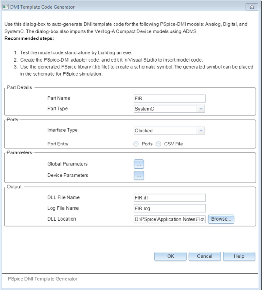
Learn to design a circuit with PSpice is a task quite simple and is enough a few pages of any manual available on line to do it. What can be confusing is the number of files with different extensions that belong to this great tool of electronic simulation. This is due to the history of PSpice, which initially developed to be used in PC by Microsim passed after to OrCAD which was at last acquired by Cadence. The original CAD Microsim was Schematics. After, the program was provided with a design tool more advanced, Capture, maintaining the ability to still use Schematics.
Schematics image:
PSpice library list is an useful tool for all PSpice users, because it’s a first approach to check if the SPICE model component they are looking for, is present in the libraries supplied with PSpice. In the list libraries there are three categories: Analog, Digital and Mixed Signal. Very useful is the possibility to search a specific component. This tutorial will briefly guide you towards creating a custom library with a previously created schematic as a component in the new library. The aim is to create a file with a.olb extension which contains the schematic as a placeable part in the OrCAD schematic environment, with PSPICE functionality included to describe the circuit. Sampling of notations that PSPICE recognizes. PSpice Notation PSpice Notation 103 K E3 10-3 m E-3 106 Meg (not M) E6 10-6 u E-6 109 G E9 10-9 n E-9 10-12 p (pico) E-12 10-15 f (femto) E-15 Your schematic is now complete! Save your schematic - -From the main menu: File-Save. 1 Place part icon.
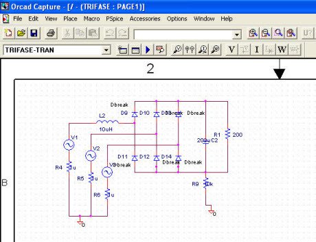
Capture image:
Fortunately, the syntax used to describe a component remained the same, and all libraries with mathematical models, are the . LIB. Creating the design of a circuit with PSpice Schematics, the project will be composed of a schematic file .SCH, a control file .CIR and a circuit description file .NET both automatically generated from Schematics, and files .INC containing subcircuits, to be included in the project. The libraries containing the mathematical models to be added to the project are always .LIB, while libraries that contain graphic symbols associated with the mathematical models are the .SLB.
By using the tool of OrCAD Capture, the main project file becomes the .OPJ, and symbolic libraries are now .OLB. In short, in Schematics a component is completely defined by libraries .LIB and .SLB while in OrCAD Capture by the couple .LIB an .OLB.

Currently most of designers use OrCAD Capture for the circuits design, however, the same Capture has a tool to convert project designed with Schematics and convert .SCH and .SLB in .OPJ and .OLB. We ‘ll see how in a dedicated article.
PSPICE Links (Updated Sept. 14, 2010)
*The current supported version of PSPICE is sold by Cadence under their OrCAD product line. You can download a demo CD from their website here:
The “Capture and PSPice only” option is all that you would typically need for circuit simulation.
. The full version is installed in the Broun Hall computer labs. The supported schematic entry tool is Capture. This replaces the older schematic entry tool called Schematics. For those who would still like to use Schematics, see the information below. Another excellent simulator using the SPICE engine is LTSpice, which is freely available from Linear Technologies here:
At this writing the current version is LTSpice IV.


*How can I get a version of PSPICE using Schematics?
- Legacy versions of PSPICE using Schematics for schematic capture are available as described below. They are reportedly unstable under Windows later than XP (e.g., Vista, 7).The two versions are: 9.1 (free student version) and 9.2 (“professional” version – no longer supported).
* Where can I get my own copy of PSPICE using Schematics? (the student version 9.1 is free).
*Download locally from Dr. Roppel's web site (file name = 91pspstu.exe). This is the student version 9.1. When you install the student version, be sure to choose SCHEMATICS as your interface, not CAPTURE. (Note: the file size is about 28 MB)
*Obtain a copy of the freshman computing initiative (FCI) CD, which includes PSPICE on Disk 1. This is the student version 9.1. When you install the student version, be sure to choose SCHEMATICS as your interface, not CAPTURE.
INSTRUCTION, DOCUMENTATION, AND EXAMPLES
*Bill Dillard's PSPICE Tutorial, Version 9 / Schematics, Sept. 2000, 27 pagesPDF (301K)Word (2.74M)
*Dr. GuofuNiu’s Capture TutorialJNT file(you might need to download Microsoft’s free JNT viewer)PDF file(coming soon)
*One source for complete PSPICE manuals: http://www.ece.uncc.edu/manuals/
* Anatomy of a PSPICE output file - dc BJT example
* How to edit the parameters of a diode in PSPICE and find the Q-point
Library Pspice Schematics
* Simulation of a PTAT (Proportional to Absolute Temperature) BJT circuit over temperature
-includes modifying BJT parameters, changing temperature, and handling library file errors
Library For Pspice Schematics Diagram
*Monte Carlo simulation of a BJT 4-resistor bias network.
Pspice Library File
*Half-Wave Rectifier simulation example dochtml